

GPM Microwave Imager (GMI)
GMI Overview
The Global Precipitation Measurement (GPM) Microwave Imager (GMI) instrument is a multi-channel, conical- scanning, microwave radiometer serving an essential role in the near-global-coverage and frequent-revisit-time requirements of GPM. The instrumentation enables the Core spacecraft to serve as both a precipitation standard and as a radiometric standard for the other GPM constellation members.
The GMI is characterized by thirteen microwave channels ranging in frequency from 10 GHz to 183 GHz. In addition to carrying channels similar to those on the Tropical Rainfall Measuring Mission (TRMM) Microwave Imager (TMI), the GMI carries four high frequency, millimeter-wave, channels near 166 GHz and 183 GHz.
With a 1.2 m diameter antenna, the GMI provides significantly improved spatial resolution over TMI.
Microwave Imager Channels
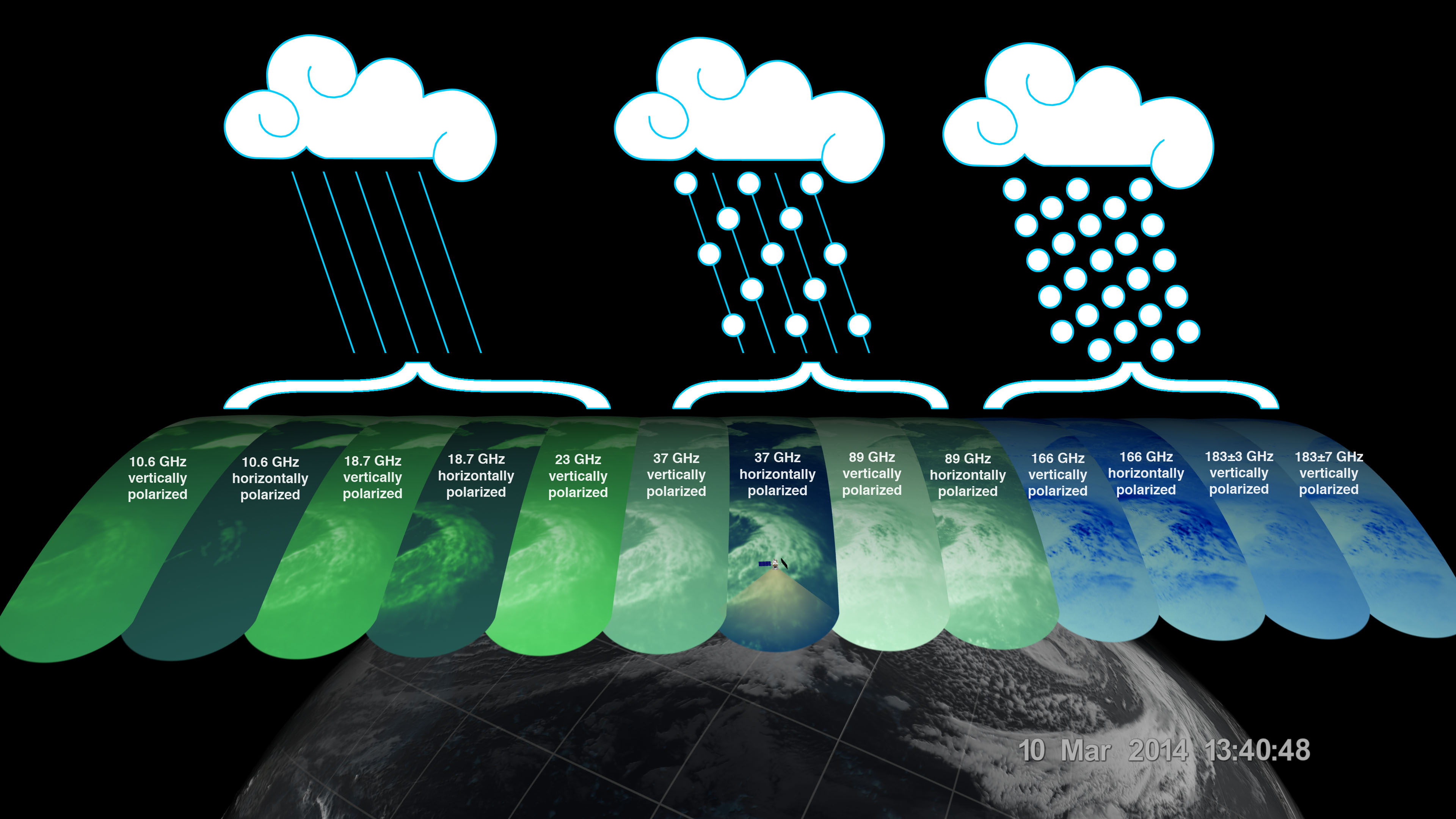
The GPM Microwave Imager (GMI) has a swath 550 miles (885 kilometers) wide, giving it a broad view of cyclones and other storm systems. The GMI instrument has 13 channels, each displayed in this visualization of the data. Each channel is sensitive to a different frequency of microwave energy naturally emitted from or affected by precipitation. As depicted by the graphic, the five channels on the left are sensitive to heavy and moderate rainfall. The four channels in the center sense precipitation mixtures of both snow and ice within the clouds. The mixed layers are often the result of ice or snow melting into rain as it falls. The four channels on the right are sensitive to water vapor and snowfall. Multiple channels in each category ensure that GMI captures as full a range as possible of precipitation types.
The data from GMI is used as a reference standard for an international network of partner precipitation-measuring satellites known as the GPM Constellation. The data from the GPM Core Observatory and these partner satellites are unified into a single global precipitation dataset called IMERG, which is updated every three hours.
Scan Geometry
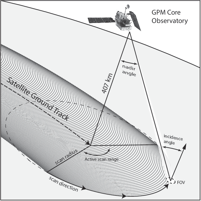
Diagram of the conical scanning geometry of the GPM Microwave Imager (GMI).
The off-nadir angle defining the cone swept out by the GMI is set at 48.5 degrees which represents an earth-incidence-angle of 52.8 degrees.The earth-incidence angle of the GMI was chosen to be identical to that of the TMI to maintain similar geometry. Spinning at 32 rotations per minute, the GMI gathers microwave radiometric brightness temperature measurements over a 140 degree sector centered about the spacecraft ground-track vector. The remaining angular sector is used for performing calibration, i.e. observations of cold space as well as a hot calibration target.
The 140 degree GMI swath represents a swath of 885 km (~550 miles) on the Earth's surface. For comparison, the DPR instrument is characterized by (since 2018) a cross-track swath width of 245 km (152 miles). Only the central portion of the GMI swath overlaps the radar swath (and with approximately 67 second duration between measurements due to the geometry and spacecraft motion). These measurements within the overlapped swaths are important for improving precipitation retrievals, and in particular, the radiometer-based retrievals.
Components of the GMI
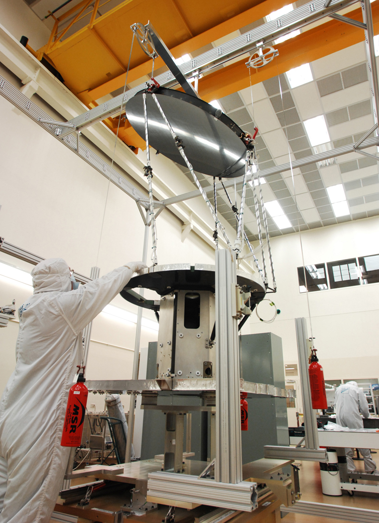
The GPM Microwave Imager (GMI) instrument under construction in a lab at Ball Aerospace & Technology Corporation. Credit: Ball Aerospace
- Instrument Spacecraft Structure - the base structure for GMI.
- Spin Mechanism Assembly - the DC motor that spins GMI.
- Slip Ring Assembly - passes receiver subsystem data from the instrument’s spinning portion to its non-spinning portion (see #15, the ICA), which then sends data to the spacecraft and then to Earth.
- Instrument Base Structure (IBS) - holds all the receiver components.
- Hot Load Tray – keeps the sun out of the hot load (#7) and helps maintain its thermal environment.
- Feed Horns - focus the reflected RF energy and send it down the wave-guides (#12) to the RF receivers (#11).
- Hot Load - provides warm temperature reference for the receivers. GMI self-calibrates by using the constant temperature references of the hot load, the cold sky reflector (#9), and the noise diodes (#12).
- Despin Assembly - holds the cold sky reflector and the hot load tray in place.
- Cold Sky Reflector - looks at deep space to provide a cold temperature reference for the receivers.
- Launch Locks - hold the IBS to the deck during launch.
- RF Receivers (attached to the IBS’s sides) - detect/measure the RF energy associated with the Earth’s precipitation (moisture from humidity, dew, snow, rain, and so on).
- Wave-guides, Noise Diodes, Mixer-Preamplifiers, RF Coaxial Cables - the wave-guides and RF coaxial cables are conduits from the feed horns (#6) to the receiver subsystem. The noise diodes provide mid-range temperature references to the three low-frequency receivers for calibration purposes. The mixer-preamplifiers are the front ends for the three high-frequency receivers.
- Sunshade and Struts - the sunshade exposes one side of the instrument to the Sun and blocks the other side from the Sun; the struts hold the main reflector.
- Main Reflector (and its support structure) - reflects the RF energy emitted from the Earth’s atmosphere into the feed horns; its coating of aluminum and then silicon oxide diffuses sunlight, which could damage the feed horns. The feed horns are located near the focal point to achieve the best combination of efficiency and beam-width performance across the various frequencies.
- Instrument Control Assembly, or ICA (attached below the Instrument Spacecraft Structure) - controls the power from the spacecraft to the instrument; controls the temperature of the instrument; controls the transmittal of science data from the receiver system; and maintains the spinning of the system through the spin mechanism assembly (#2).
Related Resources
http://www.nasa.gov/press/2014/march/...
For more information, visit http://nasa.gov/gpm
On March 10, the Core Observatory passed over an extra-tropical cyclone On March 10, the Core Observatory passed over an extra-tropical cyclone about 1055 miles (1700 kilometers) due east of Japan's Honshu Island. Satellite data shows the full range of precipitation in the storm.
This video is public domain and can be downloaded at: http://svs.gsfc.nasa.gov/goto?11508
A brief animated look at the different types of remote sensing techniques that NASA uses to study the Earth.
This video is public domain and can be downloaded at: http://svs.gsfc.nasa.gov/goto?11877